Key Takeaways
- Material Selection: PA12 and PA11 are excellent for snap-fits due to their flexibility and high elongation at break.
- Tapered Design: Taper the base of the cantilever hook to distribute stress evenly and prevent snapping.
- Clearance: Leave a 0.3mm to 0.5mm gap between the hook and the mating groove to account for SLS tolerances.
Introduction
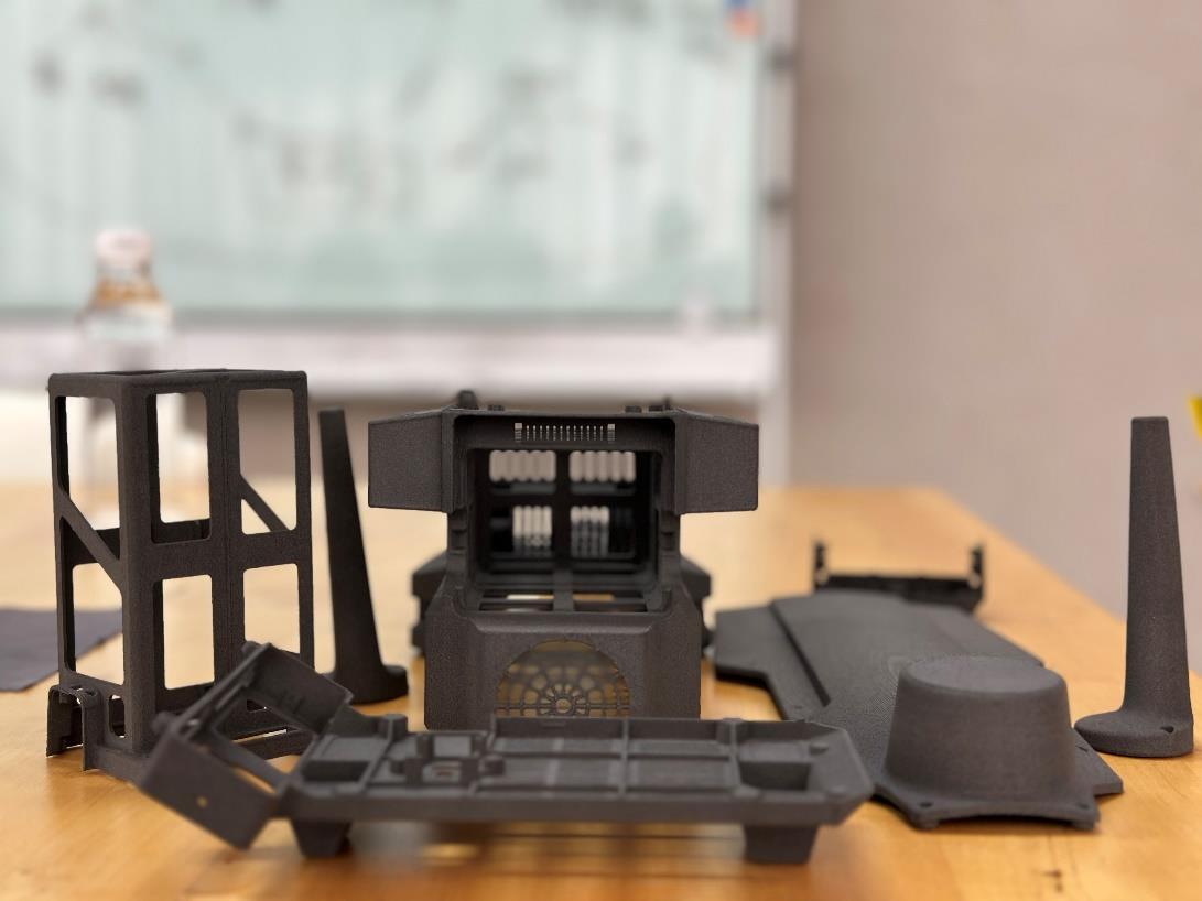
Snap-fit joints are one of the most efficient ways to assemble plastic parts without the need for screws, adhesives, or ultrasonic welding. Because Selective Laser Sintering (SLS) utilizes durable thermoplastics like Nylon PA12 and PA11, it is an excellent technology for producing functional, reusable snap-fits. However, designing them for 3D printing requires specific considerations.
The Mechanics of a Snap-Fit
The most common type of snap-fit is the cantilever hook. It consists of a protruding beam (the cantilever) with a hook at the end. As the parts are pushed together, the beam deflects, allowing the hook to slide past a lip and snap into a mating groove.
Design Guidelines for SLS Snap-Fits
1. Choose the Right Material
- PA12: Good for general-purpose snap-fits that will be assembled once and rarely taken apart.
- PA11: The superior choice for reusable snap-fits (like battery compartment covers) because its higher elongation at break allows it to flex repeatedly without fatiguing.
- Avoid Glass-Filled Nylon (PA12GB): It is too stiff and brittle; the hook will likely snap off rather than bend.
2. Taper the Cantilever Beam
When a cantilever beam bends, the stress is concentrated entirely at its base. If the beam has a uniform thickness, it is highly prone to breaking at the root. Solution: Taper the beam. Make the base of the cantilever thicker and gradually thin it out towards the hook. This distributes the bending stress evenly along the entire length of the beam, drastically increasing its durability.
3. Add Generous Fillets
Never use sharp 90-degree internal corners at the base of the cantilever. Sharp corners act as stress concentrators and will cause the snap-fit to shear off immediately. Always add a generous fillet (radius) at the root of the beam.
4. Design for SLS Tolerances
SLS parts have a slightly powdery surface finish and a standard tolerance of ±0.3mm. If you design the hook and the groove with zero clearance, the friction and tolerances will make it impossible to assemble.
- Clearance: Leave a gap of 0.3mm to 0.5mm between the sides of the hook and the mating groove.
- Deflection Angle: Ensure the hook does not need to deflect more than 10-15 degrees during assembly to prevent exceeding the material's yield strength.
Print Orientation
In SLS, parts are strongest in the X-Y plane. To ensure the snap-fit does not break along the layer lines, orient the part so that the cantilever beam lies flat in the X-Y plane. If the beam is printed vertically along the Z-axis, the bending force will pull directly against the layer adhesion, leading to premature failure.
Conclusion
By tapering the beam, adding fillets, and respecting SLS tolerances, engineers can design robust snap-fit joints that eliminate the need for external fasteners. This not only reduces the bill of materials (BOM) but also significantly speeds up the assembly process.
Related Case Studies
See how we have delivered results in similar projects
 Industrial
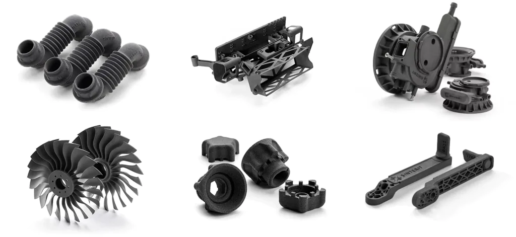
Precision Small Parts Production
Batch production of precision small parts for multiple industry clients with complex geometries.
 Industrial
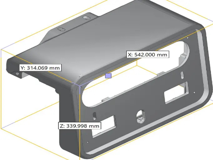
Industrial Robot Gripper
Custom end-of-arm tooling for industrial robots with complex internal channels.
 Medical
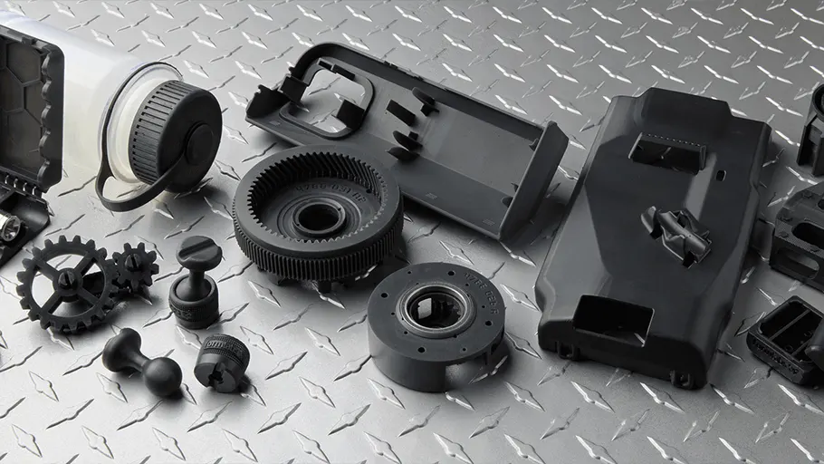
Spinal Orthosis Solution
Custom 3D printed spinal braces providing personalized solutions for scoliosis patients.