
Good SLS design starts by defining function, interfaces, risks and acceptance criteria before choosing dimensions. Wall thickness, holes, clearances, text, orientation and surface finish depend on the exact material grade, machine and process route, geometry, build position, post-processing and measurement method. Use supplier DFM guidance as a starting point, then qualify critical features with drawings, representative parts and agreed inspection—not with universal internet values.
SLS design for manufacturing (DFM) is the process of adapting a part to polymer powder-bed fusion while preserving its required function, interfaces, inspectability and validation plan. It connects CAD geometry to material, production, depowdering, finishing and acceptance requirements.
Why were the old “10 universal rules” removed?
The previous version listed fixed wall thicknesses, hole sizes, clearances, angles, roughness values and response-time promises without identifying a material grade, machine, orientation, geometry or measurement method. Those numbers could be mistaken for guaranteed capability.
ISO/ASTM 52911-2 addresses design for laser-based powder bed fusion of polymers. ASTM F3091/F3091M provides a framework for requirements and component integrity for plastic powder-bed-fusion parts. NIST’s AMB2018-04 PA12 benchmark examined multiple build dimensions and measurements, demonstrating why process and specimen conditions belong in the evidence boundary.
The revised checklist keeps the useful engineering questions and removes unsupported universal limits.
1. What should be defined before changing the geometry?
Start with:
- part function and failure consequence;
- loads, motion, temperature, chemicals, moisture, UV and cleaning;
- mating parts, datums, fits, seals, bearings, inserts and fasteners;
- cosmetic surfaces and prohibited finishing zones;
- quantity by prototype, pilot and repeat stage;
- critical dimensions, inspection methods and functional tests.
If these inputs are unknown, geometry changes may optimize the wrong requirement. Use the end-use qualification checklist when the part will remain in service.
2. How should walls, ribs and transitions be reviewed?
Review wall thickness together with unsupported span, aspect ratio, curvature, local mass, junctions, orientation, load path and material behavior. Separate structural walls from cosmetic covers and powder-containment surfaces.
Prefer gradual transitions and radii where loads change direction. Ribs can be useful, but they also change local mass, cooling and powder-removal access. Ask the supplier to identify thin, broad, tall or abruptly changing regions, then test the critical design under representative conditions.
Do not publish or accept one minimum thickness as a production guarantee for every grade and geometry.
3. How should holes, pins, text and small features be specified?
Small features are affected by nominal size, orientation, nearby mass, edge condition, post-processing and the way they are measured. For each important feature:
- state whether it is functional, cosmetic or identification-only;
- add the controlled dimension and datum to a drawing;
- define whether finishing may alter the edge or surface;
- specify the inspection method and acceptance rule;
- use a feature coupon or pilot part when the design is sensitive.
For text and logos, provide the actual font or vector geometry and define readability from an agreed viewing condition. Avoid converting font points into a universal printed-feature capability.
4. How should mating holes, fits and fasteners be designed?
Do not copy a generic hole table into a production drawing. Clearance, transition and interference fits depend on both mating parts, assembly method, material condition, orientation, post-processing and measurement condition.
Mark datums and controlled interfaces, state the mating hardware or part number, and identify whether drilling, reaming, inserts or another secondary operation is allowed. For repeated assembly, review the threaded-insert guide.
Validate sensitive fits with representative hardware and a documented sample before scaling the quantity.
5. How should hollow parts and powder removal be planned?
Every enclosed or internal region needs a cleaning strategy. Review:
- opening size and number;
- cavity volume and path length;
- bends, branches, dead ends and narrow transitions;
- powder and finishing route;
- tool, air or vacuum access;
- cleanliness and inspection acceptance.
Place openings where powder can be reached and where inspection is possible. Two openings may improve access in some geometries, but no fixed diameter or count guarantees complete depowdering. If residual powder is unacceptable and the route cannot be inspected, redesign or split the part.
6. Can clearances or moving assemblies use a universal value?
No. Print-in-place gaps depend on the material, process, orientation, feature length, surrounding geometry, powder removal and required motion. A gap that separates in one coupon may bind in a larger or differently oriented assembly.
Define the motion, load, friction, cleaning and service requirements. Test a representative clearance ladder or pilot assembly using the intended process and finish. Consider separate parts when inspection, cleaning, wear replacement or assembly control is more important than consolidation.
7. How should snap-fits and flexible features be developed?
Treat a snap-fit or living hinge as a load-bearing feature, not a material-family shortcut. Define assembly deflection, retention load, number of cycles, temperature, chemicals, moisture, notch geometry and failure mode.
Shortlist the exact grade using current documentation, then use calculation or simulation appropriate to the project and test representative printed features. The PA12 vs PA11 guide explains why family names alone do not establish ductility or service life.
8. Why do orientation and build position matter?
Orientation can affect feature resolution, surface appearance, distortion risk, measurement and mechanical evidence. Build position and surrounding thermal history may also matter. NIST’s PA12 benchmark explicitly studied builds along multiple dimensions and reported several physical measurements.
Identify surfaces or axes that control function, but allow the manufacturing engineer to review nesting and process constraints. If orientation is mandatory, put it in the order and define how it will be recorded. If orientation sensitivity is unknown, include it in the validation plan rather than promising an “optimal” universal angle.
9. How should surface finish and post-processing be specified?
Describe the required outcome and measurement instead of relying on words such as “smooth” or “production finish.” State:
- as-built, blasted, dyed, smoothed, coated or painted route;
- color reference and acceptable visual variation where relevant;
- protected datums, threads, seals and bonding areas;
- edge-rounding and dimensional concerns;
- cleanliness, roughness or appearance method when controlled.
Do not transfer a roughness range from another material, machine or test method. Request a reference sample or measured result when finish is consequential. Review available routes on the services page.
10. What should be included in the DFM file package?
Send:
- native or neutral CAD plus the authoritative drawing;
- revision, units and quantity breaks;
- exact material or functional property priorities;
- datums, critical dimensions, fits and mating hardware;
- load, environment and failure consequence;
- finish, color, masking and cleanliness requirements;
- inspection, test and documentation needs;
- target date, packaging and destination.
The model should be closed and free of unintended self-intersections, but mesh resolution is a file-quality choice—not a universal dimensional capability. State which file governs if CAD and drawing disagree. Use the RFQ preparation guide before submitting files for review.
Primary references and evidence boundary
- ISO/ASTM 52911-2:2019: Design for Polymer Laser-Based Powder Bed Fusion
- ASTM F3091/F3091M: Powder Bed Fusion of Plastic Materials
- NIST AMB2018-04: PA12 Powder Bed Fusion Benchmark
These sources support the design framework and the need to define process and measurement conditions. They do not establish a universal TPM3D wall thickness, tolerance, roughness, clearance, lead time or service-life guarantee.
Frequently Asked Questions
What wall thickness should an SLS part use?
There is no universal wall thickness that applies to every SLS part. Required thickness depends on the exact material grade, wall span, geometry, orientation, load, environment, finish and acceptance test. Mark structural and cosmetic walls in the CAD, then confirm limits through supplier DFM review and representative testing.
What tolerance can SLS hold?
SLS tolerance must be agreed for the specific machine, material, geometry, orientation, build position, post-processing and measurement method. Put critical dimensions and datums on a drawing, define the inspection condition and method, and use coupons or pilot parts when a fit is sensitive. Do not apply one website tolerance to every feature.
How large should powder escape holes be?
Escape-hole size and count depend on cavity volume, path length, turns, powder behavior, cleaning method and whether trapped powder is acceptable. Provide accessible openings and avoid blind networks, then ask the manufacturer to confirm depowdering access. A universal hole diameter cannot guarantee complete cleaning.
Can SLS print moving assemblies in one build?
Some moving or interlocking assemblies can be candidates for print-in-place production, but clearance, powder removal, orientation, geometry and finish must be reviewed together. Use a representative test piece or pilot assembly and define the required motion, load and cleaning acceptance before approving production.
What files are needed for an SLS DFM review?
Send a controlled CAD model plus a drawing or requirement sheet with revision, units, quantity, exact material or property priorities, critical dimensions and datums, mating hardware, finish, environment, inspection, test, packaging, destination and target date. Identify which file controls if the model and drawing conflict.
Related Case Studies
See how we have delivered results in similar projects
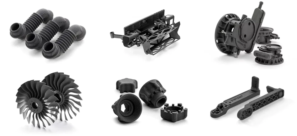 Industrial
Precision Small Parts Production
Batch production of precision small parts for multiple industry clients with complex geometries.
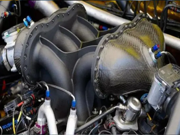 Industrial
Heavy Machinery Base Components
Lightweight base components for heavy machinery with high strength and excellent vibration damping.
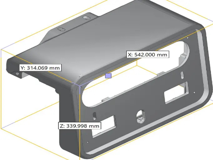 Industrial
Industrial Robot Gripper
Custom end-of-arm tooling for industrial robots with complex internal channels.