
Key Takeaways
- Material selection controls fatigue life: PA11 is usually the preferred SLS material for living hinges because it has better ductility and repeated-flex behavior than standard PA12.
- Geometry must reduce strain concentration: hinge thickness, length, fillets, and wall transitions matter more than simply making the hinge thin.
- Orientation and first-use conditioning matter: the hinge should be oriented to support bending loads, then gently cycled before full functional testing.
- RFQ notes should include the use case: tell your supplier how often the hinge will open, the expected angle, and whether it is for prototype validation or end-use service.
Introduction
A living hinge is a thin flexible web that connects two more rigid sections of a part, allowing the assembly to bend without a separate pin, screw, or hardware component. It is common in injection-molded polypropylene products, but it can also be useful in SLS 3D printing when the design is handled carefully.
For product development teams, a living hinge can reduce part count, simplify assembly, and speed up testing. Instead of printing two shells and assembling them with a mechanical hinge, the designer can often build the flexible feature directly into the SLS part. That advantage is especially valuable during early engineering validation, low-volume production, and products that need customized geometry.
However, a living hinge is not just a thin area in CAD. If the material, thickness, transition radius, and orientation are wrong, the feature may crack during the first bend. Successful SLS hinge design requires a balance between flexibility and controlled strain.
The Material Rule: Start with PA11
For most SLS living hinge applications, PA11 should be evaluated before PA12. PA12 is a strong general-purpose SLS material, but it is comparatively stiff for repeated bending. It may work for one-time movement or light demonstration, but it is usually not the safest option for a hinge expected to survive repeated opening and closing.
PA11 is more suitable because it is more ductile and better suited to flexible features. This makes it a stronger candidate for:
- living hinges
- flexible tabs
- repeated-use clips
- snap-fit features with larger deflection
- wearable or handheld products that need a softer response
That does not mean every PA11 hinge will automatically work. Material selection only gives the design a better starting point. The geometry still needs to manage bending strain correctly.
Design Guidelines for SLS Living Hinges
1. Hinge Thickness
The hinge web is the most critical area. If it is too thick, it will resist bending and may crack at the root. If it is too thin, it may be weak, porous, or inconsistent after printing and finishing.
A practical starting range for PA11 SLS living hinges is often 0.3 mm to 0.6 mm, with about 0.4 mm commonly used as an early design target. The best value still depends on hinge length, part size, powder/material behavior, finishing route, and expected use.
Use this range as a design starting point, not as a universal guarantee. For production-intent parts, the hinge should be tested with the real opening angle and cycle requirement.
2. Hinge Length and Bend Radius
The hinge needs enough length to bend gradually. A very short hinge forces the material to fold sharply, concentrating strain in a narrow zone. A longer web creates a larger bending radius and reduces the risk of cracking.
For many small SLS parts, a hinge web length of 1.5 mm to 3 mm is a useful starting range. Larger parts or 180-degree folds may need more length. The goal is not just to make the hinge flexible, but to keep the material from stretching beyond a safe strain level during bending.
3. Smooth Transitions
Never connect a thin hinge directly into a thick wall with a sharp inside corner. That transition becomes the first crack point. Instead, use generous fillets and gradual thickness changes.
Good hinge transitions should:
- remove sharp 90-degree corners
- blend thin and thick zones smoothly
- avoid abrupt stiffness changes
- protect the root of the hinge from local stress concentration
This is especially important when the hinge is connected to a rigid cover, enclosure, snap feature, or latch.
4. Keep the Hinge Path Clear
A hinge can be well designed but still fail if nearby geometry blocks the bend. Before printing, check the folded position in CAD. Make sure neighboring walls, ribs, bosses, or cable-routing features do not force the hinge to overbend.
For functional prototypes, it is also worth adding a small amount of clearance around the moving region. This helps account for tolerance, finishing, dyeing, and real assembly behavior.
Print Orientation and Process Review
SLS parts are more isotropic than many other 3D printing processes, but orientation still matters for flexible features. A hinge should be oriented so the bending load is not trying to split layer interfaces or pull the thinnest section apart in the weakest direction.
In many cases, the hinge should lie flat in the X-Y plane so the flexible web has the best chance of behaving consistently during bending. This should be reviewed together with the supplier because build packing, part thickness, surface finish, and thermal behavior can also influence the final result.
Post-Processing and First-Use Conditioning
After printing, cleaning, and finishing, a living hinge should not be forced immediately to its maximum angle. A safer approach is to gently cycle the hinge a few times before full loading. This helps reveal early issues and conditions the bend path.
If the hinge feels stiff or starts whitening, cracking, or tearing at the root, stop testing and review the design. Common fixes include increasing hinge length, improving fillets, switching material, reducing the opening angle, or splitting the hinge into multiple flexible segments.
What to Include in an RFQ
When asking for an SLS living hinge quote or DFM review, include more than just the CAD file. The supplier should understand how the hinge will be used.
Useful notes include:
- expected opening angle
- number of expected cycles
- whether the part is for prototype, pilot, or end-use production
- whether the hinge must stay closed, snap shut, or only flex during assembly
- required finishing, dyeing, or coating
- any mating parts or assembly constraints
This information helps the supplier judge whether the hinge should be printed as designed, modified, or converted into a separate mechanical hinge.
Final Takeaway
Designing living hinges for SLS requires more than reducing wall thickness. The best results come from matching PA11 material behavior with the right hinge thickness, bend radius, smooth transitions, and orientation strategy.
Need help checking a living hinge before printing? Send your CAD file, target opening angle, and expected cycle requirement to TPM3D for an SLS DFM review before the first build.
Related Case Studies
See how we have delivered results in similar projects
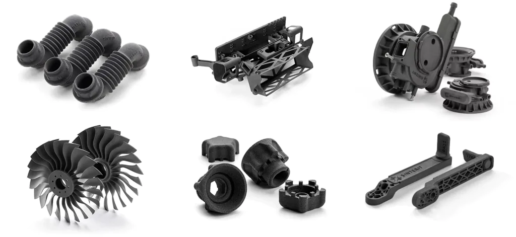 Industrial
Precision Small Parts Production
Batch production of precision small parts for multiple industry clients with complex geometries.
 Industrial
Industrial Robot Gripper
Custom end-of-arm tooling for industrial robots with complex internal channels.
 Medical
Spinal Orthosis Solution
Custom 3D printed spinal braces providing personalized solutions for scoliosis patients.