SLS 3D printing for orthotics and prosthetics gives engineering and clinical manufacturing teams a practical way to produce customized, lightweight, and repeatable components from patient-specific digital data.
The value is not simply that a brace, socket, helmet, or insole can be printed. The larger advantage is the complete digital workflow: scan, design, validate, manufacture, finish, inspect, and reproduce the same device when needed.
Medical use requires application-specific validation, qualified materials, documented production controls, and compliance with the regulations that apply in the target market. This article is a manufacturing overview, not medical advice.

Why digital manufacturing matters in O&P
Traditional orthotic and prosthetic production often involves casting, manual forming, trimming, grinding, and repeated fitting. Skilled craftsmanship remains essential, but a digital process can reduce repetitive manual steps and preserve design data.
A typical workflow includes:
- Capturing patient geometry with a 3D scan
- Correcting and designing the device in specialist CAD software
- Applying local thickness, flexibility, ventilation, and fastening features
- Performing engineering and clinical review
- Manufacturing the device with a qualified powder-bed process
- Depowdering, finishing, inspection, fitting, and documentation
The resulting CAD file also becomes a controlled digital record that can support revisions or replacement production. HP describes similar scan-to-production workflows for orthotics and prosthetics and presents applications made with PA11 and PA12 materials. Review HP's orthotics and prosthetics application overview.
Custom fit without dedicated tooling
Every patient's geometry is different. SLS can manufacture one-off or low-volume customized parts without creating a dedicated mold for each design.
This is especially useful for:
- Ankle-foot orthoses and hand braces
- Customized insoles and foot orthoses
- Protective helmets and facial devices
- Prosthetic socket prototypes and test components
- Covers, fairings, connectors, and non-implant accessories
Because loose powder supports the part during printing, engineers can integrate complex curves, perforations, cable paths, fastening features, identification marks, and local reinforcement without conventional support structures.
For broader geometry rules, use our SLS design guidelines for engineers.
Lightweight and breathable geometry
Comfort depends on more than reducing mass. The device must distribute loads appropriately, avoid sharp pressure points, manage heat and moisture, and remain practical to clean.
SLS allows designers to incorporate:
- Strategically placed ventilation openings
- Lattice or perforated regions
- Local ribs around high-load areas
- Smooth transitions between rigid and flexible sections
- Rounded edges near the body
- Integrated straps, slots, clips, and fastening interfaces
These features should never be added only for appearance. Lattice size, open area, wall thickness, edge radius, and cleaning access all need engineering review.
A lightweight design that removes material from the wrong region can become uncomfortable or unsafe. Load paths, expected motion, user weight, impact conditions, and fastening forces must be considered before production.
Selecting PA11, PA12, or TPU
Material selection should start with required mechanical behavior and regulatory documentation, not with a default powder.
PA11 for ductility and repeated movement
PA11 is commonly considered when a component needs higher ductility, impact resistance, or repeated flexing. EOS describes laser-sintered PA 1101 as a bio-based PA11 material with high ductility, impact resistance, and elongation at break. See the official EOS PA11 material data.
Potential applications include dynamic braces, flexible clips, protective features, and parts that experience repeated movement.
PA12 for dimensional stability
PA12 is often suitable for rigid housings, fixtures, covers, prototypes, and device components that prioritize dimensional consistency and balanced mechanical properties.
TPU for soft or elastic elements
TPU may be relevant for cushioning, flexible interfaces, pads, and selected lattice structures. It requires different design rules and post-processing considerations from nylon.
Our PA12 versus PA11 material guide provides a practical starting point. Final selection must also consider skin-contact requirements, cleaning chemicals, sterilization or disinfection methods, fatigue, environmental exposure, and supplier documentation.
Variable stiffness through geometry
One of the most useful design opportunities is controlling stiffness with geometry rather than assembling many different materials.
Engineers can adjust:
- Wall thickness
- Rib placement
- Perforation density
- Lattice cell size
- Curvature
- Section transitions
- Hinge or flexure geometry
For example, a brace may require a more supportive region near one joint and greater flexibility in another. These differences can sometimes be created in a single part by changing local geometry.
However, variable stiffness must be validated through simulation, bench testing, and fitting. Claims such as fatigue life, load capacity, or long-term durability should be based on the exact material, machine parameters, orientation, post-processing, and device design.
Production repeatability and traceability
A digital workflow can improve repeatability, but only when the production process is controlled.
For professional O&P manufacturing, consider documenting:
- CAD revision and patient/device identifier
- Material batch and refresh history
- Machine and build record
- Part orientation and nesting
- Post-processing route
- Dimensional or visual inspection results
- Fit and functional validation
- Cleaning and packaging procedure
The article how to prepare a better SLS RFQ explains the information a manufacturing partner needs before reviewing a project.
Design checklist before requesting a quote
Before submitting an orthotic or prosthetic component, provide:
- STEP, STL, or 3MF file
- Device type and intended function
- Required quantity and replacement expectations
- Material preference or required properties
- Critical load areas and flex zones
- Skin-contact or biocompatibility requirements
- Cleaning, disinfection, and environmental exposure
- Desired color and surface finish
- Critical dimensions and inspection method
- Applicable regulatory or documentation requirements
Do not assume that a material marketed for medical applications automatically makes the final device compliant. Compliance applies to the complete material, process, design, post-processing, documentation, and intended use.
Conclusion
SLS 3D printing for orthotics and prosthetics can support customized geometry, lightweight structures, digital traceability, and scalable production without patient-specific tooling. Its success depends on controlled design, qualified materials, practical cleaning and finishing, and validation of the final device.
For a manufacturing assessment, upload non-confidential CAD files through our engineering-reviewed SLS quotation form. TPM3D can review geometry, PA11 or PA12 selection, wall thickness, lattice manufacturability, finishing, and production documentation requirements before quotation.
Related Case Studies
See how we have delivered results in similar projects
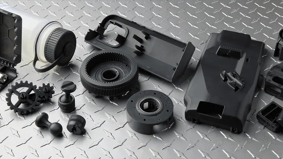 Medical
Spinal Orthosis Solution
Custom 3D printed spinal braces providing personalized solutions for scoliosis patients.
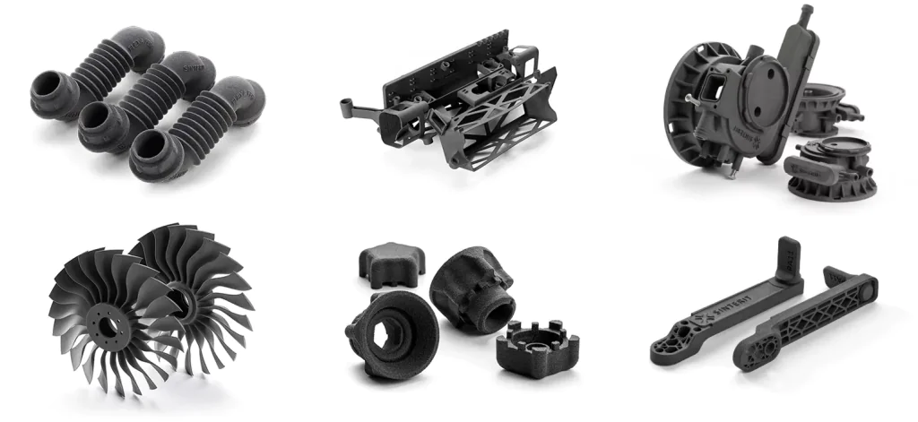 Industrial
Precision Small Parts Production
Batch production of precision small parts for multiple industry clients with complex geometries.
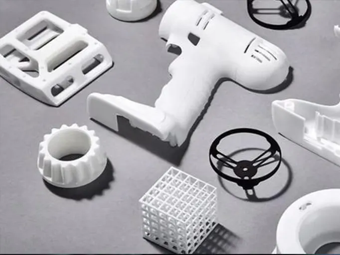 Automotive
 Prototype Parts
Functional automotive prototype parts for design validation and aerodynamic testing.