Introduction
Cable clips and routing features often look like small details in CAD, but they can decide whether an assembly feels engineered or frustrating. A cable that is forced into a sharp corner, trapped behind a stiff tab, or difficult to service can create failure risks long after the printed part itself passes inspection.
SLS is well suited for integrated cable management because it can produce custom routing channels, clips, tabs, windows, and internal guides without tooling. This is useful for robotics, industrial electronics, medical device housings, UAV systems, handheld instruments, and test equipment.
The design goal is simple: hold the cable securely without damaging it, make assembly repeatable, and leave enough access for inspection or service.
Where SLS Cable Features Add Value
SLS cable routing features are useful when a product needs:
- custom internal cable paths
- low-volume or pilot production housings
- integrated clips instead of separate fasteners
- lightweight brackets or electronic enclosures
- fast design iteration before injection molding
- functional prototypes that need real assembly testing
Because SLS nylon has a useful balance of strength and toughness, it can support local flexible features. But flexibility should be designed intentionally. A cable clip that is too stiff may crack or damage the cable. A clip that is too thin may relax, deform, or fail during assembly.
Design Priorities
1. Avoid Sharp Contact Edges
Any surface that touches a cable should be softened. Sharp internal corners can cut insulation, especially when the product vibrates or when the cable is pulled during service.
Good practice includes:
- adding radii at cable contact points
- avoiding knife-edge ribs
- using wider bearing surfaces where possible
- keeping rough post-processed areas away from sensitive cable jackets
This is especially important for thin wires, sensor cables, coaxial lines, and cables that may move during use.
2. Control Clip Flexibility
A retention tab needs enough flexibility to open during assembly, but enough stiffness to hold the cable after installation. This balance depends on material, tab length, thickness, and root radius.
For many SLS nylon features, the easiest way to make a clip more forgiving is not simply to make it thinner. It is usually better to lengthen the flexible arm, add a smooth root radius, and avoid abrupt transitions.
If the clip must be opened repeatedly, consider PA11 or a more ductile design. If the clip only needs to capture the cable once, PA12 may be sufficient depending on geometry.
3. Leave Assembly Access
A cable feature can be technically printable but still difficult to use. During CAD review, check whether a technician can actually push the cable into the clip with fingers or simple tools.
Ask these questions:
- Can the cable be inserted without forcing it at an unsafe angle?
- Is there room for fingers, tweezers, or assembly tools?
- Can the cable be removed for service?
- Does the clip block nearby screws, inserts, sensors, or connectors?
Assembly access is often where a good SLS prototype provides the most value. It lets teams discover practical service issues before tooling.
4. Design Around the Real Bend Path
Cables do not follow perfect CAD splines. They bend with a minimum radius and they respond to connector position, stiffness, and installation sequence.
A strong routing design should guide the cable along its natural path rather than forcing it into a tight corner. For stiff cables, add more clearance and a larger bend radius. For flexible signal wires, small clips may work, but avoid over-compression.
5. Consider Vibration and Long-Term Service
If the product operates in a machine, vehicle, drone, or handheld device, vibration can turn a small edge into a long-term wear point. The cable may slowly rub against the printed surface.
To reduce this risk:
- avoid hard pinch points
- use multiple gentle guides instead of one aggressive clamp
- keep cables away from sharp screw bosses or insert areas
- consider additional sleeves or grommets for demanding environments
Material Notes
PA12 is often a good starting point for general routing features because it is stable, durable, and familiar for engineering teams. PA11 becomes more attractive when the clip needs repeated flexing or when the feature behaves more like a living hinge or snap-fit.
Glass-filled nylon is usually not the first choice for flexible cable clips because the added stiffness can reduce deflection tolerance. It may still be useful for the main housing while local cable features are redesigned to avoid large flexing.
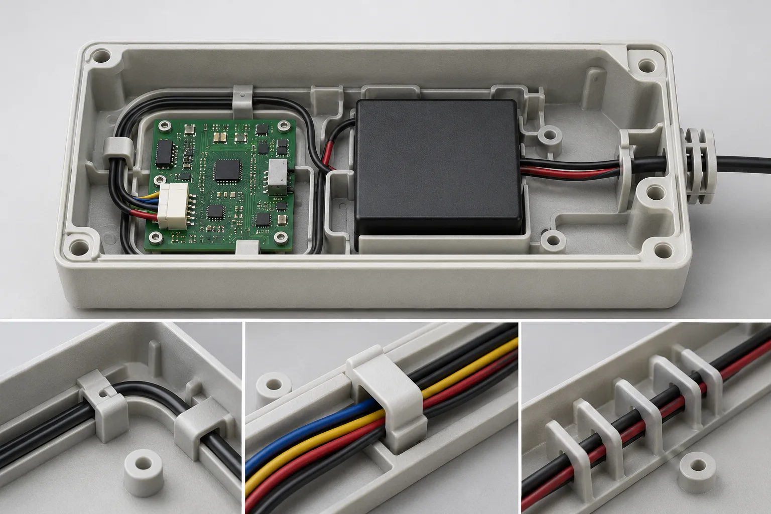
DFM Checklist for Cable Routing Features
Before sending the design for SLS printing, check:
- Are cable contact edges radiused?
- Is the clip root blended smoothly?
- Is there enough installation access?
- Does the real cable bend radius fit the available space?
- Will finishing, dyeing, or coating reduce clearance?
- Are service cycles or repeated opening required?
- Are nearby threaded inserts or screws adding local stress?
Final Takeaway
Good cable features reduce assembly friction, protect cables, and make products easier to service. They are small details, but they often reveal whether an enclosure or functional prototype has been designed around real use.
Need help reviewing cable clips or internal routing features for SLS production? Send TPM3D your CAD file, cable diameter, assembly notes, and service requirements for a practical DFM review.
Related Case Studies
See how we have delivered results in similar projects
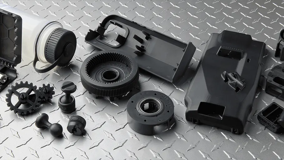 Medical
Spinal Orthosis Solution
Custom 3D printed spinal braces providing personalized solutions for scoliosis patients.
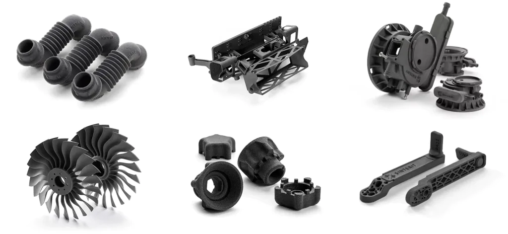 Industrial
Precision Small Parts Production
Batch production of precision small parts for multiple industry clients with complex geometries.
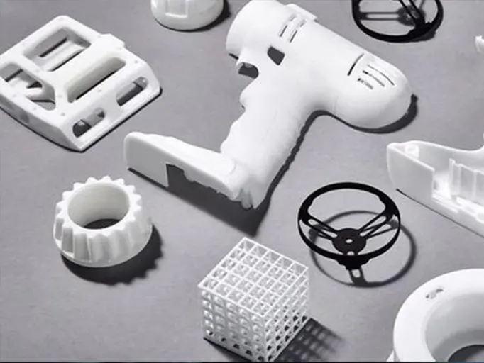 Automotive
Automotive Prototype Parts
Functional automotive prototype parts for design validation and aerodynamic testing.